2 Module 2 · Advanced · 3–5 hours
Water Tank Level & Valve
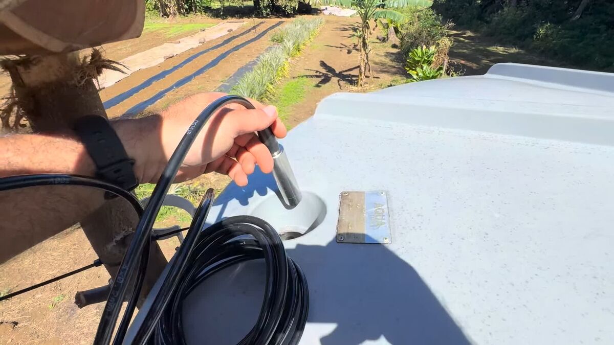
A sealed probe on the tank floor feels the weight of the water above it, and a solenoid valve on the outlet lets the system open and shut the irrigation line.
A sealed probe on the tank floor, reading depth in millimetres through to Node-RED — comms, register map and ruler calibration all confirmed. The valve rides on the same node, on the relay's switched side, behind a dead-man timer that shuts it whatever the network says.
- Parts
- $157
- Build time
- 3–5 hours
- Steps
- 9
- Board
- ESP8266
Why you would want this
- Know the tank is getting low before you run out
- Open and shut the irrigation line from anywhere, or on a schedule
- Keep a record of water use across days and weeks
- Never irrigate from an empty tank — the level and the valve are on the same node
How it goes together
What you will need
| Picture | Part | What it does | NZ$ | Link |
|---|---|---|---|---|
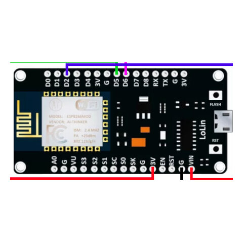 |
ESP8266 NodeMCU v3 (ESP-12E) | The small computer that runs the node | $5.77 | Buy ESP8266 NodeMCU v3 (ESP-12E) ↗ |
 |
QDY30A submersible pressure probe
Buy the RS485 variant. The same listing sells 4–20 mA, 0–5 V and 0–10 V outputs, and only RS485 works with this guide. Check the options before you pay. |
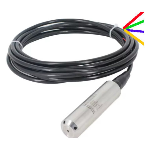
Sits on the tank floor and measures the depth of water above it | $93.12Variant priced: 5 m range, 8 m cable, RS485 output. A different range changes the price. | Buy QDY30A submersible pressure probe ↗ |
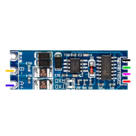 |
MAX485 / HW-0519 RS485-to-TTL module
The listing ships two different boards. The HW-0519 is auto-direction and needs no DE pin; the classic breakout has DE/RE and costs you a GPIO. Both work — but only the HW-0519 leaves you a spare pin for the valve relay. |
Lets the ESP8266 speak RS485 to the probe | $0.86The blue TTL-to-RS485 board, single piece. | Buy MAX485 / HW-0519 RS485-to-TTL module ↗ |
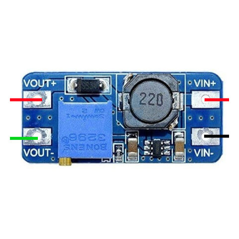 |
MT3608 boost converter
Set it to 18 V with NOTHING on the output, before the probe is ever connected. |
Steps 12 V up to the 18 V the water probe needs | $2.49 | Buy MT3608 boost converter ↗ |
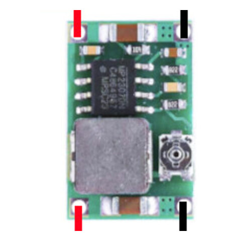 |
Mini360 buck converter (MP2307)
Fine for a sensor node at a couple of hundred milliamps. Do NOT use one to charge a phone — it misbehaves above ~1.5 A in a hot box. That job wants the 3 A synchronous buck in Module 1. |
Steps the pack's 12 V down to 5 V for the ESP8266 and RS485 board | $3.65 | Buy Mini360 buck converter (MP2307) ↗ |
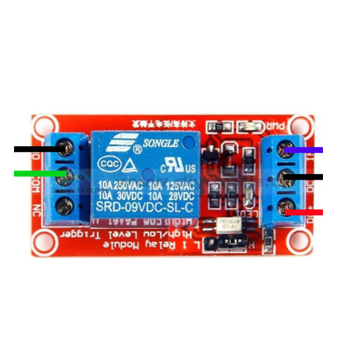 |
1-channel 5 V relay module | Lets the 3.3 V ESP8266 switch the 12 V valve | $4.56 | Buy 1-channel 5 V relay module ↗ |
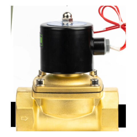 |
12 V solenoid valve, normally closed
Normally-closed is the safety property this module rests on: no power = shut. Also check the minimum pressure differential — a pilot/servo valve needs ~0.2 bar and will not open on a low gravity tank no matter how good your wiring is. |
Opens to let water out of the tank and into the irrigation line | $9.01The 12 V variant. The same listing's 220 V mains variant is cheaper and is not what this module uses. | Buy 12 V solenoid valve, normally closed ↗ |
|
1N5819 flyback diode
Not optional. Without it the ESP8266 reboots — but only when the valve closes. |
Absorbs the spike the valve coil throws when it shuts | $4.62A lot of 50, 1N5819. One node needs one. | Buy 1N5819 flyback diode ↗ | |
| Jumper wires | Connects everything | $5.50New Zealand retail — the sheet has no AliExpress row for these. | — | |
| USB cable | Powers the ESP8266 and loads code onto it | $10Bought as a lot of ten for $100. | — | |
| Hose fittings for the valve | Joins the valve into your irrigation line | ~$8.50 | — | |
| Waterproof container | Protects the electronics | ~$8.50 | — | |
| Approximate total | $156.58 | |||
Prices are NZD, read off the linked listing on 2026-08-08. A figure marked ~ is an estimate — we have no listing for that part yet, so treat it as a placeholder rather than a quote. Prices move, and shipping to a small island is its own line item. Links are not affiliate links and we get nothing if you use them.
Wiring
Water bus — QDY30A
- Baud
- 9600
- Frame
- 8N1
- Slave
- 1
| Probe wire | From | Goes to | Note |
|---|---|---|---|
| Red | probe red | MT3608 OUT+ (18 V) | 18 V — this wire and nothing else. 18 V into the MAX485 or the ESP destroys both. |
| Green | probe green | MT3608 OUT− + common ground | Prime suspect for an intermittent read. One ground, not two. |
| Blue | probe blue | HW-0519 A | A+ — note this is the OPPOSITE colour convention to the soil probe. |
| Yellow | probe yellow | HW-0519 B | B− |
Module 2 as this guide builds it
wire this onefirmware/water-level/water-level.ino
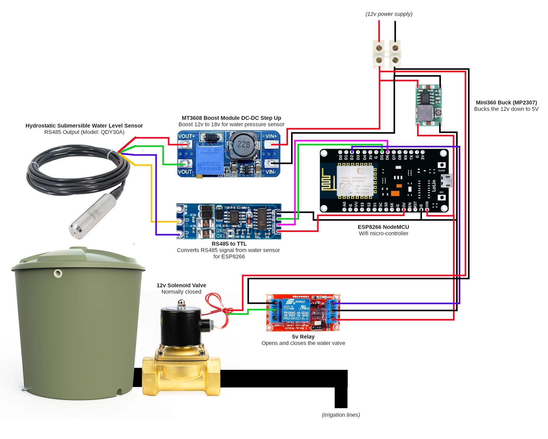
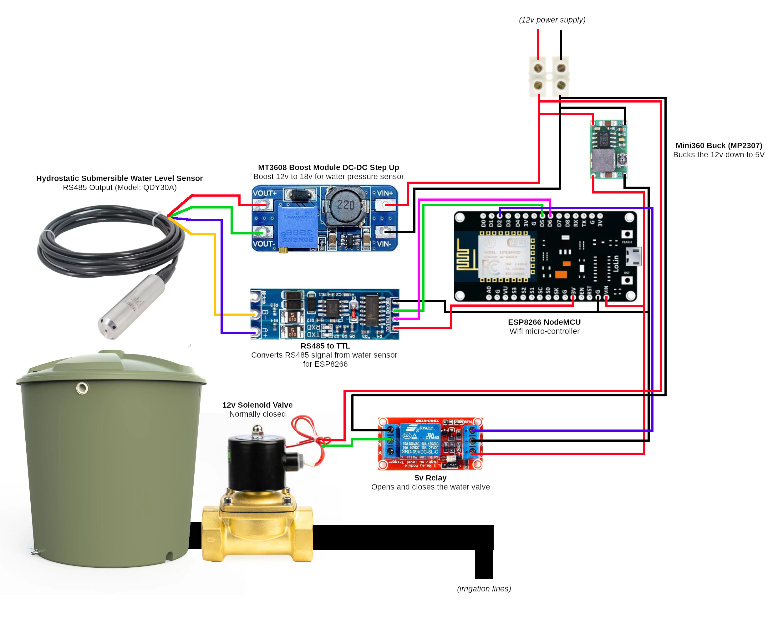
This is the assignment in the wiring picture above, and it leaves D2 free for the valve relay. On a classic DE/RE breakout, join DE and RE and drive them from D1; an auto-direction HW-0519 needs no DE pin at all.
| RS485 pad | ESP pin | GPIO | Direction |
|---|---|---|---|
| RXD / RO | D5 | GPIO14 | in — data toward the ESP |
| TXD / DI | D6 | GPIO12 | out — data toward the probe |
| relay IN | D2 | GPIO4 | out — opens and shuts the valve |
| DE + RE | D1 | GPIO5 | classic breakout only — omit on HW-0519 |
| VCC | 3V3 | — | power |
| GND | GND | — | common ground star |
Ian's deployed farm-node (water + valve)
firmware/farm-node/farm-node.ino
Swapped relative to the build above — the pins follow how the board was actually soldered on 2026-07-19, and the firmware follows the iron. NEVER run water-level.ino on this board: it drives D1 as DE, and D1 here is the water probe's TXD, so it would clamp the driver onto the bus and the probe could never reply.
| RS485 pad | ESP pin | GPIO | Direction |
|---|---|---|---|
| RXD | D7 | GPIO13 | in — data toward the ESP |
| TXD | D1 | GPIO5 | out — data toward the probe |
| relay IN | D2 | GPIO4 | out — opens and shuts the valve |
| VCC | 3V3 | — | power |
| GND | GND | — | common ground star |
| Register | Means | Scaling | Type |
|---|---|---|---|
| 0x0004 | Depth above the probe | 1 count = 1 mm | signed int16 |
Both RS485 board variants work and the firmware handles both — but the auto-direction HW-0519 is what leaves D2 free for the valve relay. A classic DE/RE breakout spends an extra GPIO on direction, and the budget is only five.
The valve side
The valve never touches the logic side of the board. It hangs off the relay's switched contacts, which are electrically isolated from the ESP8266 — that isolation is exactly why 12 V cannot backfeed your laptop while you bench it. The only way to put valve current onto USB is to wire the coil to the ESP's 5 V pin. Don't.
| Relay pin | Goes to | Note |
|---|---|---|
| VCC | 5 V | From the Mini360's 5 V output — or VBUS if the board is on USB only. The ESP 5 V pin you aren't feeding is dead: VIN floats on USB, VBUS reads ~3 V on the pack. |
| GND | GND | Common ground with the ESP. |
| IN | D2 (GPIO4) | The one safe pin left once the bus has taken D5 and D6. |
| COM / NO | valve coil | NO, so relay unpowered = valve unpowered = valve shut. |
Build it, step by step
-
Set both converters before anything else is connected
This is the one step where you can actually destroy something. Both modules' trimmers ship at a random setting, and the boost feeds an 18 V rail.
Connect 12 V to IN+ / IN− with nothing on the output. Put a multimeter across OUT+ / OUT−. Turn the MT3608's screw until it reads a steady 18.0 V, and the Mini360's until it reads 5.0 V. Power down. Now connect the probe and the ESP8266.
-
Wire it up
Four wires out of the probe, four wires between the RS485 board and the ESP8266, and three to the relay. The tables below are generated from the same pin data as the wiring cheatsheet, so they cannot drift apart.
-
Load the code
The firmware is
firmware/water-level/. Install the Arduino IDE, addesp8266in Boards Manager, and select NodeMCU 1.0 (ESP-12E). There are no libraries to install.Copy
config.example.htoconfig.hand edit that — never the sketch itself. Start withBENCH_MODE 1so it prints over serial and skips WiFi entirely: bring the sensor up before WiFi joins the list of things that can be broken.# always compile --upload. A bare `upload` flashes a stale .bin arduino-cli compile --upload \ --fqbn esp8266:esp8266:nodemcuv2 -p /dev/ttyUSB0 firmware/water-level -
Zero it
Read the probe dry, sitting in air. It will not read zero — ours read about 26, which is 26 mm of water that does not exist. That is normal and within spec.
Write that number down. Your depth is
reading − dry_reading. Do this once at install; if readings drift over months, do it again. -
Check it actually moves
Lower the probe into a bucket. The number should climb clearly, hold steady when it stops moving, and fall back when you lift it out. If it does not respond to depth, stop — nothing after this will work.
-
Wire the relay and the valve
The valve goes on the relay's switched side, never the logic side. Use the NO (normally open) contact so that relay unpowered = valve unpowered = valve shut.
12V + ────────────────► valve terminal 1 valve terminal 2 ──────► relay COM relay NO ──────────────► 12V − 1N5819 across the valve's two terminals, stripe (cathode) to the + side -
Build the safety cutoff before you leave it alone
This is the step people skip and then regret. If a command is lost, or the link drops while the valve is open, the valve stays open — and a failed poll deliberately holds the last state, so an open valve plus a dead hotspot is an open valve forever. Nothing upstream can help, because nothing upstream can reach it.
So the node enforces its own dead-man timer, independent of any command:
VALVE_MAX_OPEN_Sshuts an open valve once it has gone that long without hearing the base station say “open”. It counts from the last confirmation, not from when the valve opened, so a planned run is never cut while the link is up — the run length is set on the base station's page. It ships at 1800 s and defaults to on, so a farmer opts out of the guard rather than into it. -
Install on your tank
Lower the probe to the bottom and let it sit flat. Fit the valve into the outlet line with the flow arrow pointing the way the water goes. Protect the ESP8266, RS485 board and both converters inside the waterproof container. Measure your tank's water depth when full, once — that is what turns millimetres into “how full is my tank”.
-
Point it at the base station
Set
BENCH_MODE 0, put your hotspot's name and password inconfig.h, and leavePOST_HOSTempty. The phone running the hotspot is the node's gateway by definition, so the node works out the address itself.Test the endpoint before you ever blame the firmware:
curl -X POST http://<phone-ip>:1880/water \
  -H 'Content-Type: application/json' \
  -d '{"node":"test","ok":true,"depth_mm":500}'
Supporting files
Everything in the repository worth having on your own disk before you start — the sketch you flash, the flow you import, the datasheet you check a pinout against. Download saves the file; the path opens it on GitHub if you would rather read it first.
- sketch firmware/water-level/water-level.ino The sketch this guide builds — water level only, no libraries to install Download firmware/water-level/water-level.ino ↓
- config firmware/water-level/config.example.h Copy to config.h and edit that. WiFi, the dry-reading calibration, and BENCH_MODE Download firmware/water-level/config.example.h ↓
- sketch firmware/farm-node/farm-node.ino Our deployed node: water + master valve on one board, with OTA reflash. NOTE its pins are swapped relative to the guide — read firmware/README.md before flashing Download firmware/farm-node/farm-node.ino ↓
- config firmware/farm-node/config.example.h Config template for the deployed node, including VALVE_MAX_OPEN_S Download firmware/farm-node/config.example.h ↓
- flow flows/water-level-flow.json Node-RED flow that receives the depth readings. Import into the Module 4 phone Download flows/water-level-flow.json ↓
- tool tools/poll-water.ts Bench poller — proves the probe from a laptop before any ESP8266 exists. bun tools/poll-water.ts Download tools/poll-water.ts ↓
- doc project/bench/02-bench-water-level-rs485.md Bring-up notes from the bench: what we measured and what went wrong Download project/bench/02-bench-water-level-rs485.md ↓
- doc firmware/README.md Build and OTA procedure, and why each sketch carries its own Modbus code Download firmware/README.md ↓
- image docs/wiring-diagram-module-2-water.jpg The wiring picture at full size Download docs/wiring-diagram-module-2-water.jpg ↓
- datasheet hardware/Manual - Water Level Option A.pdf QDY30A probe manual — register map and wire colours Download hardware/Manual - Water Level Option A.pdf ↓
- datasheet hardware/Manual - MT3608 Boost.pdf MT3608 boost converter (the 18 V rail) Download hardware/Manual - MT3608 Boost.pdf ↓
- datasheet hardware/Manual - Mini360 Buck.pdf Mini360 buck converter (the 5 V logic rail) Download hardware/Manual - Mini360 Buck.pdf ↓
- datasheet hardware/Manual - TTL to RS485.pdf RS485 transceiver module — both board variants Download hardware/Manual - TTL to RS485.pdf ↓
- datasheet hardware/Manual - Plastic Solenoid.pdf Solenoid valve manual — check the minimum pressure differential Download hardware/Manual - Plastic Solenoid.pdf ↓

Or take the lot: download the whole
repository as a zip, or git clone https://github.com/sunrise-labs/farmers-iot-toolkit.git. Each sketch needs its
config.example.h copied to config.h and edited — the real
config.h is never committed, because it holds your WiFi password.
When it doesn't work
Ordered roughly by how often it has actually been the answer.
| Symptom | Almost always | What to do |
|---|---|---|
| No reading at all | A and B swapped | Swap the blue and yellow wires. This is common — try it before anything else. |
| No reading, probe cold | Not enough voltage | Meter red to green: it must read 18 V, not the raw 12 V. |
| Boost converter reads 0 V | Trimmer parked mid-range | It is 25-turn with no end stops. Keep turning, watch the meter. |
| Readings 10× off | Wrong scaling | 1 count = 1 mm. Check you are not treating it as centimetres. |
| Reading is about 65000 | Read as unsigned | It is signed int16. Readings slightly below zero are real and legitimate. |
| Reading never changes | Wrong register | It is 0x0004. |
| Readings fail randomly | No common ground | Probe green, boost OUT−, buck OUT−, MAX485 GND and ESP GND must be one rail. |
| Drifts with the weather | Breather tube blocked or wet | Keep the loose cable end dry and open to air. |
| Reads, then silent, then reads | A wire, not the firmware | Wiggle-test each one while the node polls, prime suspect green/ground. Do this before soldering anything into a box. |
| Relay clicks but the valve doesn't move | Not enough volts at the coil under load | Meter across the valve while the relay is on. A sagging pack meters fine at rest. |
| Relay doesn't click at all | Relay VCC on a dead 5 V pin | On the pack, take VCC from the Mini360's 5 V output (same rail as VIN) — VBUS only reads ~3 V there. On USB only, use VBUS — VIN floats. |
| ESP reboots when the valve closes | Missing flyback diode | Fit the 1N5819 across the valve terminals, stripe to +. |
| Valve energised, nothing flows | Below the valve's minimum pressure differential | A pilot valve needs ~0.2 bar. Check the head above it; if marginal, spec a direct-acting “0 bar” valve. |
| Valve opens on a full battery, not a flat one | Solenoid under-volted | Measure the coil current and check the pack voltage under that load, not at rest. |
How this fits with the others
Why a pressure probe and not an ultrasonic one
Nearly every beginner tutorial puts an ultrasonic sensor on the tank lid and bounces sound off the water. It is cheaper, and for a real farm tank it is the wrong tool — this module used to describe that design and we changed it deliberately. A tank is an enclosed cylinder full of reflective surfaces with a moving surface on top: the worst possible case for an echo. A pressure probe ignores every one of those problems because it does not look at the water. It sits underneath it.
| Ultrasonic, from the top | Pressure probe — this module | |
|---|---|---|
| How it measures | Times a sound echo off the surface | Feels the weight of water above it |
| Tank walls | Sound bounces off them — false readings | Doesn't care |
| Ripples, foam, debris | Scatter the echo | Doesn't care |
| Condensation on the face | Blinds it | Lives underwater anyway |
| Mounting | Needs clear line of sight straight down | Just drop it in |
| Cost | Cheaper | More |
| Power | Runs off the board | Needs 12–36 V — hence the boost converter |