Reference
Wiring cheatsheet
Every pin, wire colour, baud rate, register and voltage in the toolkit, on one page. Written to be read on a phone with a probe in your other hand, and to print onto two sheets you can tape inside the enclosure lid.
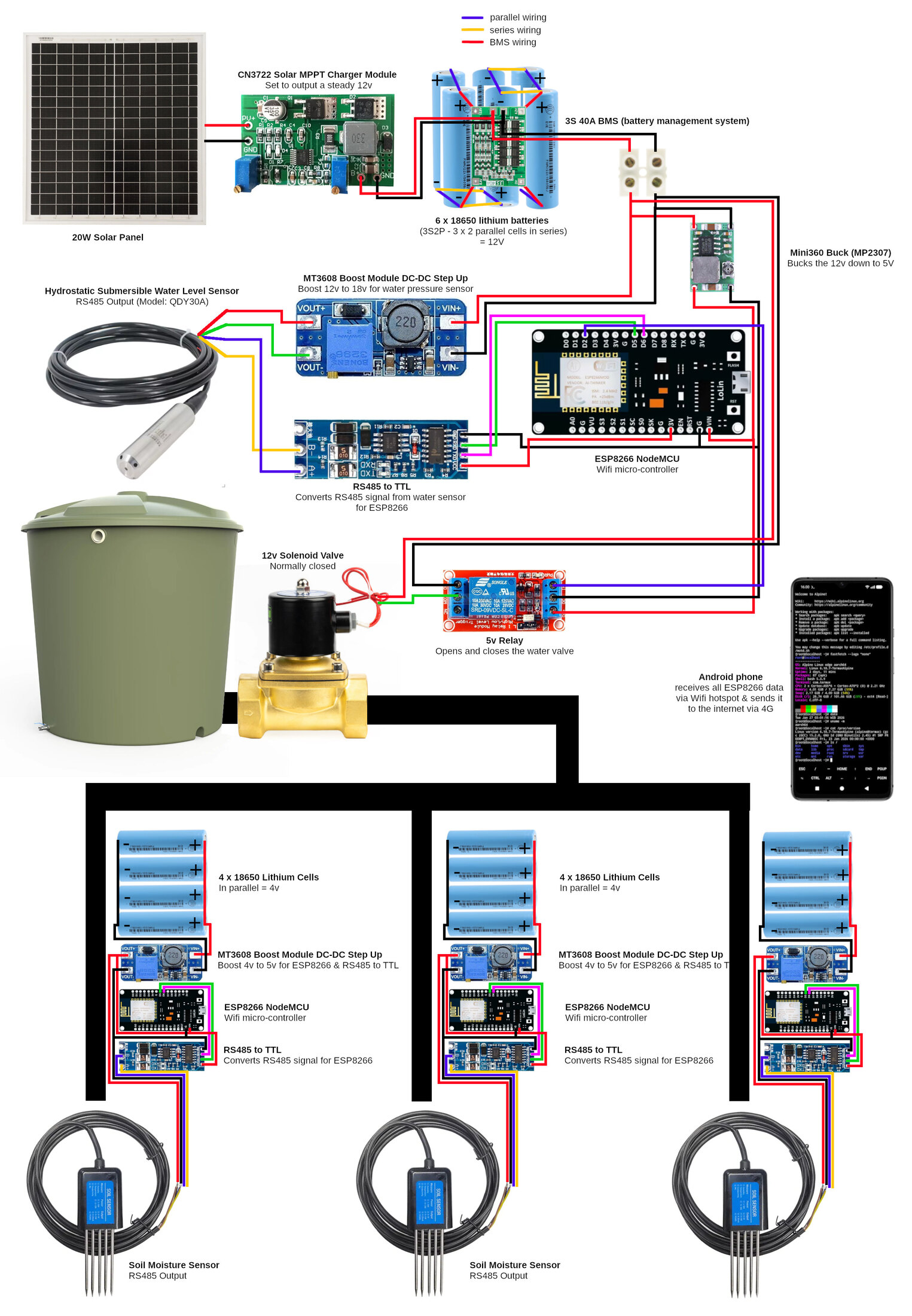
1 · The whole system, in one picture
Every module wired the way the farm actually runs. If you only print one thing, print this.
2 · The pin budget
A NodeMCU 1.0 gives you five GPIOs that are both free and safe. There is no sixth. Plan around this before you design anything.
| Pin | GPIO | Used for | Why not | |
|---|---|---|---|---|
| D1 | GPIO5 | safe | water TX on farm-node · soil TX on the bench node · DE on water-level.ino | |
| D2 | GPIO4 | safe | Module 2 valve relay IN | |
| D5 | GPIO14 | safe | Module 2 water RX · Module 3 soil TX | |
| D6 | GPIO12 | safe | Module 2 water TX · Module 3 soil RX | |
| D7 | GPIO13 | safe | water RX on farm-node · soil RX on the bench node | |
| D0 | GPIO16 | trap | deep-sleep wake only (Module 3) | No interrupts at all — it physically cannot receive SoftwareSerial. |
| D3 | GPIO0 | trap | leave alone | Boot strap — must be HIGH at boot. |
| D4 | GPIO2 | trap | leave alone | Boot strap — must be HIGH at boot. |
| D8 | GPIO15 | trap | leave alone | Boot strap — must be LOW at boot. |
3 · Module by module
One RS485 bus per node, one transceiver each — never one shared bus. Both probes ship as slave address 1 and run different bauds, so putting them together would mean writing address and baud registers on sensors we own exactly one of each, where a bad write costs you the ability to talk to the thing at all. Giving the soil probe its own ESP8266 deletes both problems, needs zero register writes, and lets it sit a hundred metres from the tank.
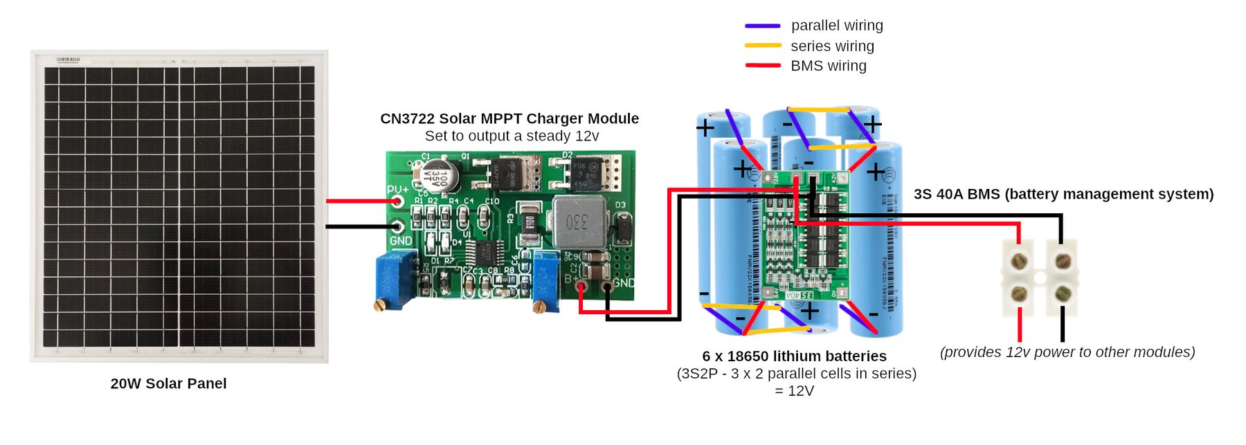
1Solar Power Pack
2Water Tank Level & Valve
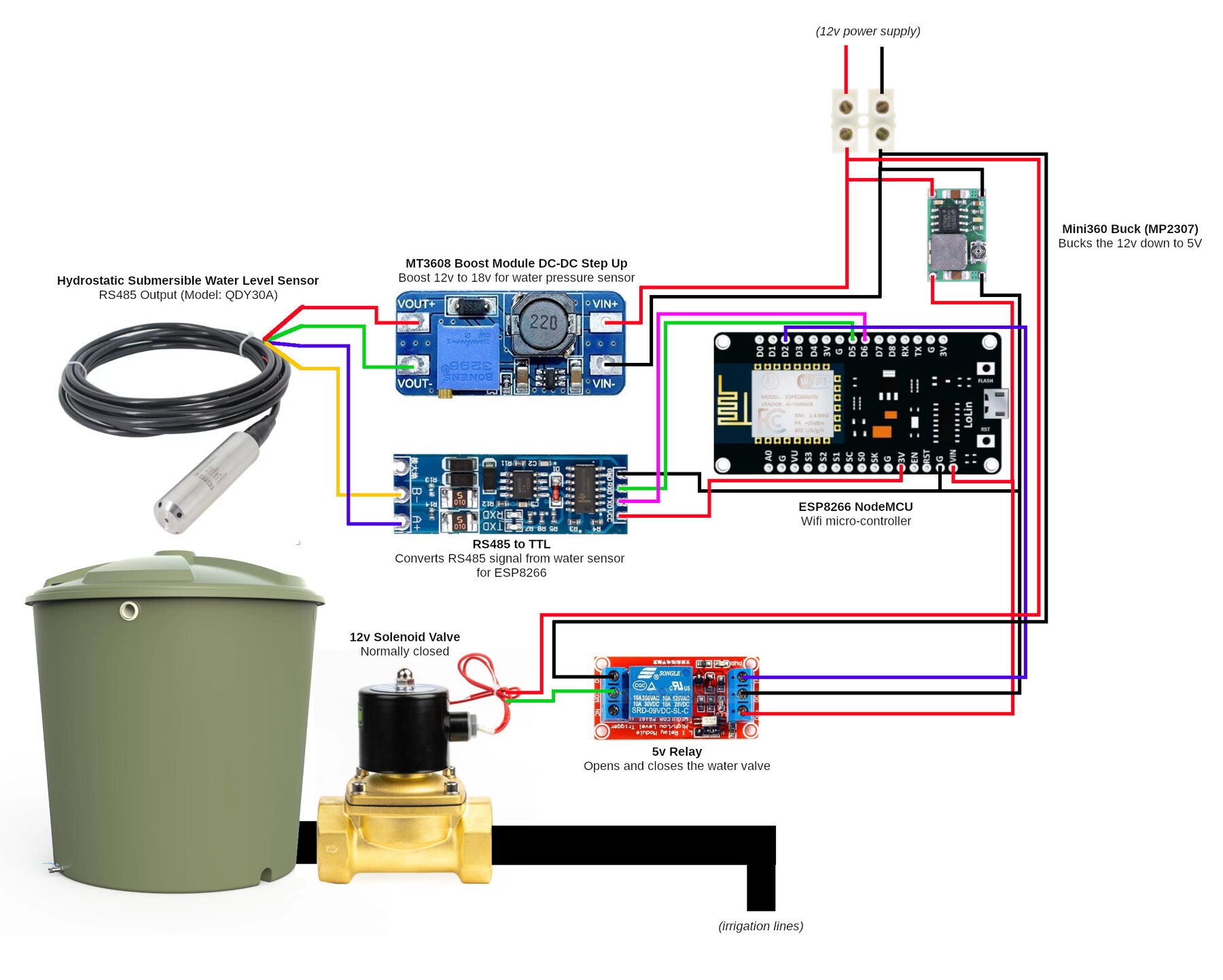
- Bus
- 9600 8N1 · slave 1
- Pins
- RXD / RO → D5 · TXD / DI → D6 · relay IN → D2 · DE + RE → D1
- Registers
- 0x0004 Depth above the probe (1 count = 1 mm, signed)
- Wires
- Red → MT3608 OUT+ (18 V) · Green → MT3608 OUT− + common ground · Blue → HW-0519 A · Yellow → HW-0519 B
- Firmware
- firmware/water-level/water-level.ino
- Note
- This is the assignment in the wiring picture above, and it leaves D2 free for the valve relay. On a classic DE/RE breakout, join DE and RE and drive them from D1; an auto-direction HW-0519 needs no DE pin at all.
3Soil Moisture Sensor
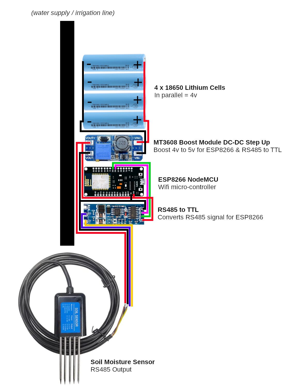
- Bus
- 4800 8N1 · slave 1
- Pins
- RXD / RO → D6 · TXD / DI → D5 · D0 → RST → D0
- Registers
- 0x0000 Moisture (÷10 → %) · 0x0001 Temperature (÷10 → °C, signed) · 0x0002 EC (µS/cm as-is)
- Wires
- Brown → boost OUT+ (5 V) · Black → boost OUT− / common ground · Yellow → HW-0519 A · Blue → HW-0519 B
- Firmware
- firmware/soil-node-sleep/soil-node-sleep.ino
- Note
- The standalone deep-sleep soil node. It also needs D0 wired to RST as the wake wire — keep that link removable, because flashing needs it disconnected.
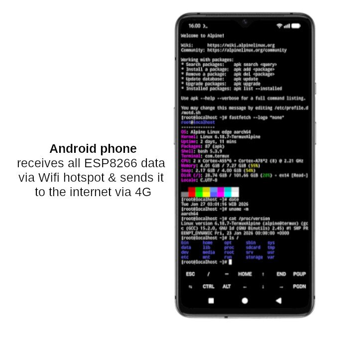
4Mobile WiFi Base Station
4 · Wire colours — the trap
The two probes use the same two colours for A and B, and they mean opposite things. Different manufacturers, no standard. This is the single easiest wiring mistake in the whole build, and it is most likely to catch you on the day you build the second module from muscle memory.
QDY30A — water
Blue = A+
Yellow = B−
Red = 18 V, green = ground
THC-S — soil
Yellow = A+
Blue = B−
Brown = 4.5–30 V, black = ground
5 · Grounding — what must be common, and what must not
One ground per node, and everything on that node shares it. On Module 2 these are all the same electrical node:
probe green (water) ── MT3608 OUT− ── MT3608 IN− ── Mini360 OUT− ── Mini360 IN−
      ── RS485 GND ── ESP GND ── pack P−
The water probe runs on the boosted 18 V rail while the ESP runs on 3.3 V — two supplies, one shared return. Random intermittent failures with wiring that “looks right” are usually this. Module 3 has the same rule on a smaller chain: probe black, boost OUT−, boost IN−, RS485 GND and ESP GND are one rail, referenced to its own 1S pack.
The two nodes do not share a ground with each other. They are separate boxes joined only by WiFi, which is exactly why a soil probe can sit a hundred metres from the tank.
Deliberately not common: when you bench the valve from a separate 12 V mains adapter, the solenoid draws through the relay's isolated switched contacts. Its current never touches USB and no common ground is wanted between the 12 V side and your laptop. That isolation is exactly why 12 V cannot backfeed the laptop.
6 · Voltages, and what happens if you get them wrong
| Rail | Value | Feeds | If it's wrong |
|---|---|---|---|
| Panel Vmp | 18.6 V @ 25 °C, ≈16.5 V hot | MPPT input | Below pack+2 V once hot and the pack charges partway forever, never balances, and quietly dies over a year. |
| Charge CV | 12.6 V | the pack | Charging is rated 0–45 °C only only. A sealed box in tropical sun exceeds that at midday. |
| Pack | 12.6 V → ~9.0 V | everything | ~70 Wh stored, ~38 Wh everyday everyday-usable. ESR 53 mΩ, so sag is state-of-charge, not load. |
| Boost | 18.0 V | water probe red wire only | 18 V into the RS485 module or the ESP destroys both. Set it with nothing on the output. |
| Soil probe | 4.5–30 V | straight off the pack | No converter needed — the pack sits inside its input range at every state of charge. |
| Logic | 3V3 | both RS485 modules | — |
| Relay | 5 V buck | relay VCC | Same rail as the ESP's VIN. Not VBUS: it is only live on USB, and on the pack it sits at ~3 V and the relay won't click. (USB-only bench: the reverse — use VBUS, VIN floats.) |
| Phone | 5.15–5.2 V | USB, D+ shorted to D− | Unshorted data pins → the phone thinks it's a computer port and takes 500 mA. This failure impersonates a solar problem. |
| Device | Power awake | Awake how often | Wh/day |
|---|---|---|---|
| Sleeping soil node | 0.6 W awake | ~5% | ~1.5 |
| Water probe + node | 0.5 W | ~5% | ~0.6 |
| Solenoid valve | ~7 W | 20 min/day | ~2.5 |
| Field gear, total | — | sleeping properly | ~5.5 |
| Android phone, plugged in | 0.7–2.0 W | 100% — cannot Doze while charging | 20–57 |
7 · Network
| Method | Path | Payload | |
|---|---|---|---|
| uplink | POST | /water | {node, ok, raw, depth_mm, valve, valve_open_s, rssi, uptime_s} |
| uplink | POST | /soil | {node, ok, moisture_pct, temp_c, ec, rssi, uptime_s} |
| downlink | GET (poll, 1 s) | /valve | "1" / "0" |
| page | GET | /page | live readings, one card per node |
| page | POST | /valve/set | sets flow.valveCmd |
8 · Bring-up order
Not arbitrary. A panel has no off switch, and a boost converter set wrong destroys a probe.
- Cover the panel. Connect the battery through the BMS to the MPPT output, then uncover. Teardown is the reverse — cover and disconnect PV first, then the battery.
- Set the MT3608 to 18 V with nothing on its output. Meter it. Only then connect the probe's red wire.
- Verify one ground with a continuity beep: probe green ↔ ESP GND ↔ P−.
- Flash with
BENCH_MODE 1and prove both probes over serial, before WiFi joins the list of things that can be broken. - Set
BENCH_MODE 0; confirm serial prints agateway :matching the phone, andPOST /water: 200 ok. - Curl the endpoint from a laptop before ever blaming firmware.
- Valve last, and only after its pull-in voltage is known.
# always compile --upload — a bare `upload` flashes a stale .bin
arduino-cli compile --upload --fqbn esp8266:esp8266:nodemcuv2 -p /dev/ttyUSB0 firmware/farm-node

# prove a probe from a laptop, before any ESP8266 exists
bun tools/poll-soil.ts  [device] [--once]     # THC-S, 4800 8N1
bun tools/poll-water.ts [device] [--once]     # QDY30A, 9600 8N1

# prove the base station, before blaming firmware
curl -X POST http://<phone-ip>:1880/water -H 'Content-Type: application/json' \
-d '{"node":"water-tank-1","ok":true,"depth_mm":500}'9 · Symptom → cause
Every fault table in the toolkit, merged. If something is not working, start here.
| Symptom | Almost always | What to do |
|---|---|---|
| No output voltage · Power | Fuse has blown | Check and replace it — then find out why. |
| Pack charges partway then stops, never reaches full · Power | Panel Vmp too low once hot | Subtract ~11% from the label Vmp and check it is ≳2 V above the pack's full-charge voltage. |
| Charges fine in the morning, stops by midday · Power | Same cause — the panel heated up and Vmp fell | Higher-Vmp panel, or fewer cells in series. |
| Panel gives far less current than its rating · Power | Facing the wrong way | In the southern hemisphere the midday sun is in the NORTH. Check Voc and Isc disconnected to confirm the panel itself is healthy. |
| BMS cuts power suddenly · Power | A cell is faulty or badly connected | Check every connection, test each cell individually. |
| Phone charges very slowly — looks like the panel is too small · Power | USB data pins not shorted | Short D+ to D− at the socket. Confirm with a USB power meter that it now draws >0.5 A. This failure impersonates a solar problem. |
| Phone charges but never reaches full on a sunny day · Power | Voltage drop in a long thin USB cable at 2 A | Shorter, thicker cable; set the buck to 5.15–5.2 V. |
| Enclosure gets very hot inside · Power | No ventilation | Vent holes on the shaded side, meshed to keep bugs out. |
| No reading at all · Water + valve | A and B swapped | Swap the blue and yellow wires. This is common — try it before anything else. |
| No reading, probe cold · Water + valve | Not enough voltage | Meter red to green: it must read 18 V, not the raw 12 V. |
| Boost converter reads 0 V · Water + valve | Trimmer parked mid-range | It is 25-turn with no end stops. Keep turning, watch the meter. |
| Readings 10× off · Water + valve | Wrong scaling | 1 count = 1 mm. Check you are not treating it as centimetres. |
| Reading is about 65000 · Water + valve | Read as unsigned | It is signed int16. Readings slightly below zero are real and legitimate. |
| Reading never changes · Water + valve | Wrong register | It is 0x0004. |
| Readings fail randomly · Water + valve | No common ground | Probe green, boost OUT−, buck OUT−, MAX485 GND and ESP GND must be one rail. |
| Drifts with the weather · Water + valve | Breather tube blocked or wet | Keep the loose cable end dry and open to air. |
| Reads, then silent, then reads · Water + valve | A wire, not the firmware | Wiggle-test each one while the node polls, prime suspect green/ground. Do this before soldering anything into a box. |
| Relay clicks but the valve doesn't move · Water + valve | Not enough volts at the coil under load | Meter across the valve while the relay is on. A sagging pack meters fine at rest. |
| Relay doesn't click at all · Water + valve | Relay VCC on a dead 5 V pin | On the pack, take VCC from the Mini360's 5 V output (same rail as VIN) — VBUS only reads ~3 V there. On USB only, use VBUS — VIN floats. |
| ESP reboots when the valve closes · Water + valve | Missing flyback diode | Fit the 1N5819 across the valve terminals, stripe to +. |
| Valve energised, nothing flows · Water + valve | Below the valve's minimum pressure differential | A pilot valve needs ~0.2 bar. Check the head above it; if marginal, spec a direct-acting “0 bar” valve. |
| Valve opens on a full battery, not a flat one · Water + valve | Solenoid under-volted | Measure the coil current and check the pack voltage under that load, not at rest. |
| No reading at all · Soil | A and B swapped | Swap the yellow and blue wires — note these are opposite to Module 2. |
| No reading at all · Soil | Wrong baud | This probe is 4800. Module 2's is 9600. Don't copy the number across. |
| Invalid CRC on every frame with mbpoll · Soil | Adapter echo, not a fault | Use bun tools/poll-soil.ts. The sensor is fine. |
| modbus exception 0x01 · Soil | Used 0x30 from the manual | The manual has a typo. The function code is 0x03. |
| Temperature reads ~65000 · Soil | Parsed as unsigned | Cast to int16_t. 0xFF9B = −10.1 °C. |
| Moisture always 0 and the probe IS buried · Soil | Air gap around the tines | Pack the soil firmly against the probe. |
| Board won't accept a flash · Soil | D0 is still linked to RST | Remove the wake link, flash, put it back. |
| Node wakes powered but unresponsive · Soil | Flash chip, not the sketch | Check the chip ID. An XMC (0x20) part is bench-proven for deep sleep here. |
| Pack goes flat in weeks, not months · Soil | The node isn't actually sleeping | Confirm the D0→RST link is fitted and the sketch reaches deepSleep. An awake ESP8266 draws ~100× its sleeping current. |
| Two nodes' readings jump around each other · Soil | Both publishing under one node name | Give each node its own name in config.h. |
| Node can't find the WiFi network · Phone | Hotspot off, or name mismatch | Check the hotspot is on and the SSID matches config.h exactly. |
| Can't open Node-RED in the browser · Phone | Node-RED isn't running | Open Termux and start it again — and check the wake-lock. |
| Dashboard shows no data · Phone | Node posting to the wrong address | Leave POST_HOST empty and let the node derive it from the gateway. |
| Flow looks healthy but nothing is scheduled · Phone | Android froze the timer | Make it event-driven; hold a wake-lock; set Termux to Unrestricted. |
| Phone battery drains fast · Phone | Hotspot + Node-RED never sleep | Keep it charged — and on solar, duty-cycle the charger, not the phone. |
| Mobile data disappearing quickly · Phone | Sending too often | Batch readings, or send summaries rather than every sample. |