1 Module 1 · Medium · 3–4 hours
Solar Power Pack
A 20 W solar panel charges six 18650 cells through an MPPT controller and a protection board. The pack hands out a steady 12 V to every other module.
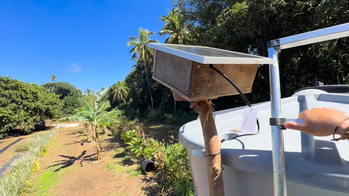
A 20 W panel, an MPPT charger and a 3S2P lithium pack behind a BMS, handing 12 V to everything else on the farm. Built, mounted on the tank stand and running — with the cell chemistry and the full energy budget worked out here.
- Parts
- $231
- Build time
- 3–4 hours
- Steps
- 6
- Board
- none — power only
Why you would want this
- Run sensors anywhere on the farm — no power outlet needed
- Free to run once it is built
- One pack can carry several sleeping nodes at once
- Sensors that sleep are almost free: ~5.5 Wh/day against a 50–60 Wh/day panel
How it goes together
What you will need
| Picture | Part | What it does | NZ$ | Link |
|---|---|---|---|---|
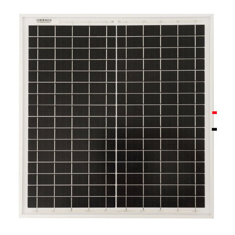 |
20 W solar panel, Vmp 18.6 V
Vmp matters more than watts. Subtract ~11% for heat and the result must still sit ≳2 V above your pack's full-charge voltage, or the pack never finishes charging. |
Charges the pack | $49.99 | Buy 20 W solar panel, Vmp 18.6 V ↗ |
 |
CN3722 MPPT solar charger | Gets the most out of the panel and charges the pack safely | $15.24 | Buy CN3722 MPPT solar charger ↗ |
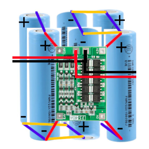 |
18650 lithium cells ×6
×6
Ours are Samsung INR18650-32E (3200 mAh). Use the real figure off the wrapper — treat unbranded or salvaged cells as 60–70% of whatever they claim. |
Store the day's sunlight — three in series, two in parallel | $120Six cells at about $20 each. | — |
 |
3S 40 A BMS protection board
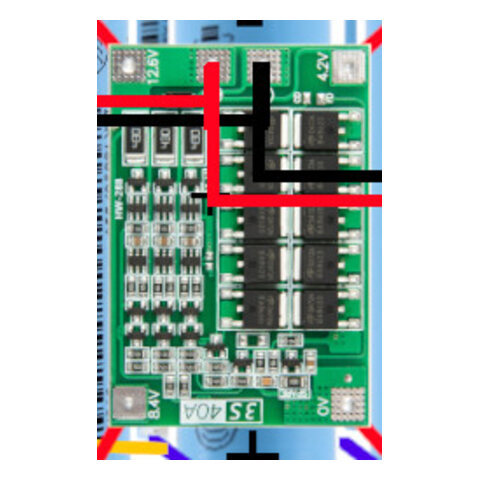
Every load taps pack+ / P−, never B−. Tapping B− silently bypasses the protection. |
Guards against overcharge, over-discharge and short circuit | $5 | Buy 3S 40 A BMS protection board ↗ |
| Battery holder or spot-welded pack | Holds the six cells in 3S2P | ~$8.50 | — | |
|
5 V / 3 A synchronous buck converter
For a phone, do not use a tiny Mini360 — it is rated 3 A and misbehaves above ~1.5 A in a hot box. Set 5.15–5.2 V and short USB D+ to D−. |
Steps the pack down to 5 V USB for the base-station phone | ~$5 | — | |
| Fuse holders + fuses | Cuts power if a leg shorts | ~$8.50 | — | |
 |
Screw terminal block | Where the other modules tap their 12 V | ~$1.70 | — |
| Weatherproof enclosure | Keeps rain, dust and sun off | ~$17 | — | |
| Approximate total | $230.93 | |||
Prices are NZD, read off the linked listing on 2026-08-08. A figure marked ~ is an estimate — we have no listing for that part yet, so treat it as a placeholder rather than a quote. Prices move, and shipping to a small island is its own line item. Links are not affiliate links and we get nothing if you use them.
Wiring
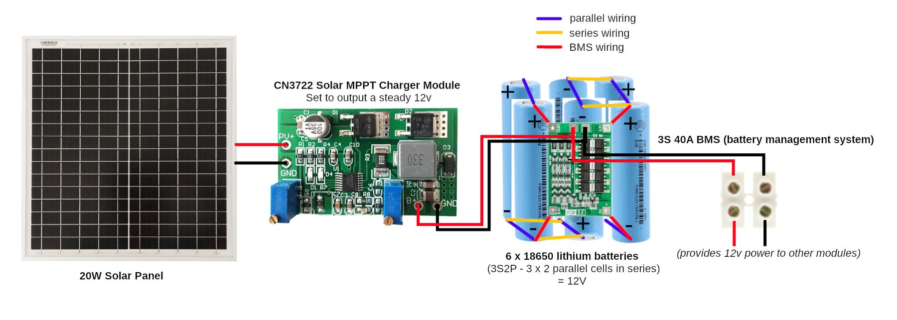
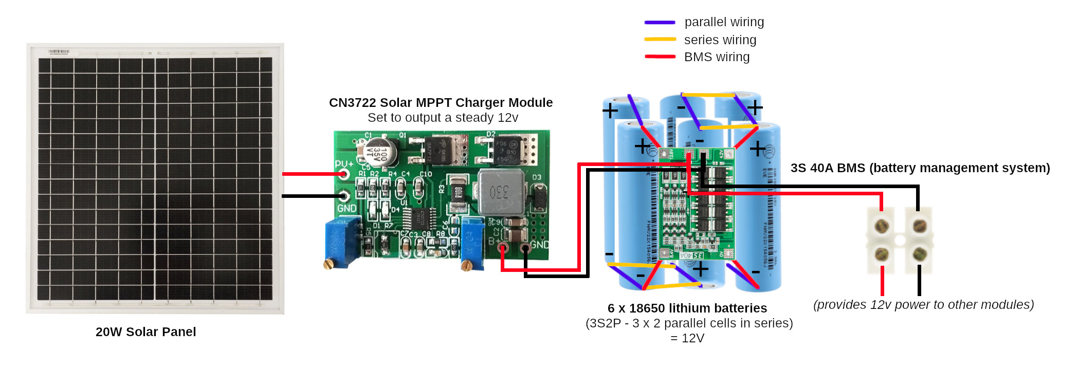
Everything hangs off one chain: panel → MPPT → BMS → pack → terminal block. The order is not negotiable, and neither is where the loads tap — pack+ / P−, on the protected side of the BMS, never B−. Tapping B− routes discharge around the protection FETs and you lose over-discharge and short-circuit protection silently.
Set the charger's CV pot to 12.6 V and its MPPT pot to the panel's hot Vmp (≈16.5 V hot), not the 18.6 V @ 25 °C on the label. The pack sits at 12.6 V full and ~9.0 V near empty, with an ESR of 53 mΩ — so voltage sag under load is telling you the state of charge, not that something is dragging the rail down.
The energy budget
This is the number that decides whether the system runs forever or dies in a week. Compare two figures in watt-hours per day: what the panel collects, and what your devices spend. Not what the battery holds — the battery is a bucket, not a tap.
| Device | Power awake | Awake how often | Wh/day |
|---|---|---|---|
| Sleeping soil node | 0.6 W awake | ~5% | ~1.5 |
| Water probe + node | 0.5 W | ~5% | ~0.6 |
| Solenoid valve | ~7 W | 20 min/day | ~2.5 |
| Field gear, total | — | sleeping properly | ~5.5 |
| Android phone, plugged in | 0.7–2.0 W | 100% — cannot Doze while charging | 20–57 |
Our ~70 Wh pack gives 56 Wh drained to 80% depth, but that is an emergency depth. Cycling that deep daily in tropical heat wears the cells out in a year or two, so plan against ~38 Wh everyday. Charging is rated 0–45 °C only; discharging −20 to 60 °C.
Build it, step by step
-
Test every cell before it goes in
Multimeter each cell: it should read between 3.0 V and 4.2 V. Discard anything below 2.5 V or that looks damaged, swollen or smells wrong.
-
Arrange the cells 3S2P and fit the BMS
Three cells in series makes ~11 V nominal (12.6 V full); two of those chains in parallel doubles the capacity. In the picture above the purple links are the parallel pairs and the yellow are the series joins.
Follow the BMS markings for B+, B− and the balance taps — the taps read ascending: 0 → 4.2 → 8.4 → 12.6 V.
-
Connect the MPPT charger and panel
Panel to the controller's PV input, pack to its battery terminals. Set the CV pot to 12.6 V and the MPPT pot to the panel's hot Vmp (~16.5 V), not the 18.6 V on the label.
-
Fuse each leg out of the terminal block
The terminal block on the right of the diagram is where Modules 2, 3 and 4 tap their power. Put a fuse between the pack and each load rather than one big fuse on the pack: 3 A is a sensible start for a sensor node, and the phone charger gets its own 2 A so a chafed USB cable cannot take your sensors down with it.
If you are charging the base-station phone from this pack, feed the 5 V/3 A buck from the protected side of the BMS and set it to 5.15–5.2 V with a meter on it.
-
Do the energy budget before you close the box
This is the most important step in this module, and the one people skip. Batteries are a bucket, not a tap. The panel fills the bucket; your devices empty it. Adding more batteries makes the bucket bigger — it does not make the tap run faster. If your devices use more each day than the panel collects, more batteries will not save you; you will just take longer to run flat.
A sunny-day surplus tells you almost nothing. Any solar system looks fine in the sun. What kills them is a run of overcast days, and in the tropics that means the wet season — not the dry months when you probably built it.
-
Charge the phone in bursts, not continuously
If you're running Module 4 off this pack, do not leave the phone plugged in. A plugged-in phone can never enter Android's Doze (it only engages when unplugged), so it runs at its awake floor forever — 20–57 Wh/day out of a panel that collects 50–60 Wh on a good day.
The trick: the phone's own battery is a second battery pack. A 5100 mAh handset holds ~19.4 Wh against the pack's ~38 Wh everyday-usable. Charge it from daytime surplus and let it coast overnight, exactly as it would in your pocket. A $3 pack-voltage relay does the whole job with no code: ON at ~12.3 V, OFF at ~11.6 V.
Supporting files
Everything in the repository worth having on your own disk before you start — the sketch you flash, the flow you import, the datasheet you check a pinout against. Download saves the file; the path opens it on GitHub if you would rather read it first.
- doc hardware/3S2P.md The pack itself: cells, voltages, charge limits and the energy budget every power figure on this site derives from Download hardware/3S2P.md ↓
- doc project/bench/03-bench-phone-power.md Runnable bench sheet for measuring what a phone actually draws over 24 h — tests 1, 2 and 6 need no special equipment Download project/bench/03-bench-phone-power.md ↓
- image docs/wiring-diagram-module-1-power.jpg The wiring picture at full size, for printing or pinching-to-zoom on a phone Download docs/wiring-diagram-module-1-power.jpg ↓
- datasheet hardware/18650-cells-INR18650-32E.pdf Samsung INR18650-32E cell datasheet — the real capacity and temperature limits Download hardware/18650-cells-INR18650-32E.pdf ↓
- datasheet hardware/Manual - MPPT Option A.pdf CN3722 MPPT charger manual Download hardware/Manual - MPPT Option A.pdf ↓
- datasheet hardware/Manual - MPPT Option B.pdf The alternative charger we costed, kept for comparison Download hardware/Manual - MPPT Option B.pdf ↓

Or take the lot: download the whole
repository as a zip, or git clone https://github.com/sunrise-labs/farmers-iot-toolkit.git. Each sketch needs its
config.example.h copied to config.h and edited — the real
config.h is never committed, because it holds your WiFi password.
When it doesn't work
Ordered roughly by how often it has actually been the answer.
| Symptom | Almost always | What to do |
|---|---|---|
| No output voltage | Fuse has blown | Check and replace it — then find out why. |
| Pack charges partway then stops, never reaches full | Panel Vmp too low once hot | Subtract ~11% from the label Vmp and check it is ≳2 V above the pack's full-charge voltage. |
| Charges fine in the morning, stops by midday | Same cause — the panel heated up and Vmp fell | Higher-Vmp panel, or fewer cells in series. |
| Panel gives far less current than its rating | Facing the wrong way | In the southern hemisphere the midday sun is in the NORTH. Check Voc and Isc disconnected to confirm the panel itself is healthy. |
| BMS cuts power suddenly | A cell is faulty or badly connected | Check every connection, test each cell individually. |
| Phone charges very slowly — looks like the panel is too small | USB data pins not shorted | Short D+ to D− at the socket. Confirm with a USB power meter that it now draws >0.5 A. This failure impersonates a solar problem. |
| Phone charges but never reaches full on a sunny day | Voltage drop in a long thin USB cable at 2 A | Shorter, thicker cable; set the buck to 5.15–5.2 V. |
| Enclosure gets very hot inside | No ventilation | Vent holes on the shaded side, meshed to keep bugs out. |
How this fits with the others
Why 3 cells in series and not 4
An earlier version of this guide said 4S2P. That was wrong, and it is worth explaining why, because the mistake is easy to repeat and it fails in a way that is hard to diagnose. A charge controller cannot push energy uphill — it needs the panel about 2 V above the pack's full-charge voltage. And a panel's Vmp drops as it gets hot: the 18.6 V on the label is measured at 25 °C, and a panel in tropical sun runs at 55–60 °C and loses ~11%. Here is the nasty part. A 4S pack on this panel does not look broken. It charges on a cool morning, settles around 15 V, and reads like a working battery. What it never does is finish — and a BMS only balances cells at the top of a full charge. So the cells drift apart over months, the weakest starts hitting cutoff early, and the pack's usable capacity quietly collapses long after you stopped suspecting the panel. The 4S failure isn't “it won't charge”. It's “it charges just enough to look fine, and destroys itself over a year.”
| Arrangement | Full charge | Panel voltage needed | A hot panel gives 16.5 V |
|---|---|---|---|
| 3S — this guide | 12.6 V | ~14.6 V | ✅ works, ~1.9 V to spare |
| 4S — the old, wrong version | 16.8 V | ~18.8 V | ❌ short by 2.3 V |